
Differential pressure (DP) gauge switches are vital devices in many applications and are used in various industries to give accurate pressure reading as well as monitoring control. It is essential that these switches are properly set for performance optimisation and systems reliability.
As CMC Technologies being an authorised distributor of Mid-West Instrument in Australia and New Papua Guinea, here is a step-by-step guide through field calibration of a Mid-West Instrument DP gauge switch to ensure you acquire all necessary information for fine tuning to your specific application requirements for our customers.
Understanding DP Gauge Switches
Mid-West Instrument offers clients to have their gauge switches set to a certain point or to the middle of the dial range at no extra cost at the factory before they dispatch your order. However, in practice it is often required to adjust the switch so that it will perform well in your installation or to adapt to new operational parameters.
DP gauge switches according to the pressure difference between two points in a system. The core working principle of these devices is that most often, they employ the flexible diaphragm design for isolation of high pressure from low pressure, and instruments/meters which convert pressure differences into both visual indications and switch actions through a magnetic coupling system.
Safety Precautions Before Adjusting
Before beginning any adjustments to your DP gauge switch, follow these critical safety guidelines:
- Verify compatibility: Check the model number and ensure the gauge is compatible with your process media and temperature.
- Confirm pressure ratings: Verify the selected pressure range (differential pressure and working pressure) is appropriate for your application.
- Disconnect power: Perform all electrical adjustments with power removed to prevent electrical hazards.
- Check for media hazards: Be aware that remaining media may present risks to personnel and environment; use appropriate precautionary measures.
- Proper installation: If installing within a pressure-tight enclosure, verify all process connections are leak-tight to prevent pressure buildup.
Field Adjustment Procedure
Tools Required:
- Non-magnetic Phillips screwdriver (recommended)
- Ohmmeter or equivalent device to monitor contact operation
- Appropriate wrenches for process connections
Step-by-Step Adjustment Process:
- Access the Switch:
- Remove the cover or access plug to reach the switch adjustment mechanism
- Do not confuse the switch access point with the actual adjustment screw
- Determine Desired Set Point:
- You can set the switch using the indicating dial as reference or with a calibrated pressure gauge
- Note that switches can typically be set within 15-95% of the full scale range (varies by model)
- Make the Adjustment:
- For setting on increasing pressure: Increase your pressure to the desired set point
- Rotate the adjustment screw to position the switch above the desired setting (switch deactivated)
- Slowly decrease the set point until the contact activates
- Follow the adjustment direction indicated on the decal (typically counterclockwise to increase set point)
- Verify Operation:
- Use an ohmmeter to monitor contact operation during adjustment
- Ensure the switch remains activated from set point to maximum PSID
Model-Specific Considerations
Mid-West Instrument offers several different models of DP gauge switches, each with specific adjustment procedures:
Model 114
- Working pressure up to 1000 PSI
- Differential pressure ranges from 0-20″ H₂O to 0-600″ H₂O
- Switch setting range (descending): 15 to 95% of full scale
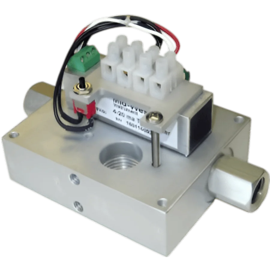
Model 130/142/240
- Working pressure up to 3000 PSI (depending on material)
- Differential pressure ranges vary by model
- Accessible switch adjustment mechanisms with clear directional indications
Model 522
- Working pressure up to 1000 PSI
- Differential pressure range: 5 PSID minimum to 50 PSID maximum
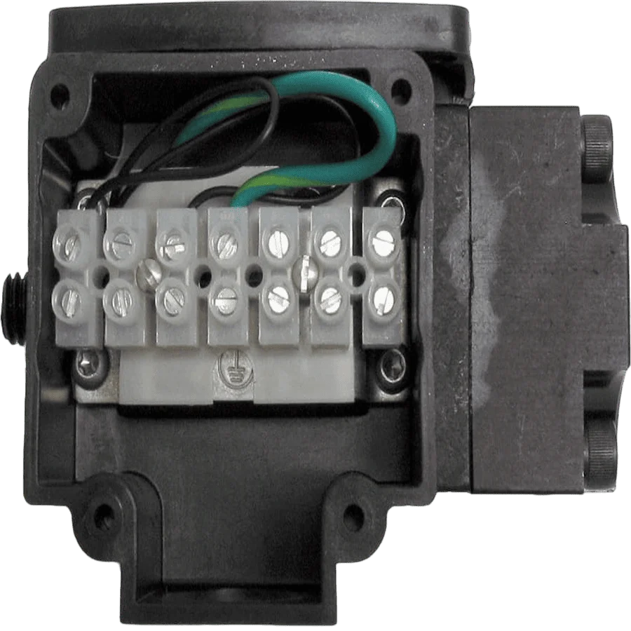
- DIN interface that conforms to DIN 43650A/ISO 4400
Troubleshooting Common Issues
If you encounter problems with gauge accuracy or switch function, check these common issues:
- Incorrect plumbing: Verify process connections are properly connected to “Hi” and “Lo” ports.
- Magnetic interference: Ensure the gauge is not installed near electromagnetic or magnetic environments, such as high current power lines.
- Mechanical issues: Verify the pointer has fluid movement as pressure increases; no movement may indicate a blown diaphragm or stuck mechanism. In this case, please make a booking with CMC to get it repaired and recalibrated.
- Electrical overload: Make sure the switch load does not exceed the specified wattage rating.
- Wiring problems: Check all electrical connections to ensure proper contact and configuration.
It is important to properly set the gauge switches in order to have correct reading and reliable control in your process applications. By using the guide provided, along with your specific model documentation from Mid-West Instrument, you can get your switch calibrations spot on for your operational needs.
As a side note, although field adjustment is possible, if you have troubling doing it on your own, please remember that CMC is here to help. In complex applications or if you come across the same problem over and over again, contacting CMC Technologies for help is advised.
By grasping the process of adjustment, and having a close look on how your DP gauge switches work can increase their lifespan and continue giving you top performance in all your industrial systems.